Difference between revisions of "Disassembling a Roomba 560"
| Line 28: | Line 28: | ||
Image:Roomba_9.JPG | By separating the elements of the brush housing, its contents become visible. Separation is obtained by flexing the two plastic arms seen on the top of the image, so that the two metal pins at their extremities come out of the corresponding holes in the blue part of the housing. As such holes pass through the blue element, the flexing is easily done by inserting a tool from the other end of the hole. | Image:Roomba_9.JPG | By separating the elements of the brush housing, its contents become visible. Separation is obtained by flexing the two plastic arms seen on the top of the image, so that the two metal pins at their extremities come out of the corresponding holes in the blue part of the housing. As such holes pass through the blue element, the flexing is easily done by inserting a tool from the other end of the hole. | ||
Image:Roomba_10.JPG | The housing two motors: one is used for brush rotation, while and the other lifts the whole brush higher from the ground when needed (e.g., the robot is on a thick carpet). The motors are mounted back-to-back: the brush motor is on the right. The right (thicker) wall of the black element is actually an enclosure housing the gear reduction for the brush motor. On the spindle of the lift motor is a grey pulley, on which a short string is wound when the brush housing is lifted from the ground. The string is terminated by a small brass cap passing through a hole in the blue part of the housing. This cap is (barely) visible at the bottom of the housing in the preceding picture. | Image:Roomba_10.JPG | The housing two motors: one is used for brush rotation, while and the other lifts the whole brush higher from the ground when needed (e.g., the robot is on a thick carpet). The motors are mounted back-to-back: the brush motor is on the right. The right (thicker) wall of the black element is actually an enclosure housing the gear reduction for the brush motor. On the spindle of the lift motor is a grey pulley, on which a short string is wound when the brush housing is lifted from the ground. The string is terminated by a small brass cap passing through a hole in the blue part of the housing. This cap is (barely) visible at the bottom of the housing in the preceding picture. | ||
| + | Image:Roomba_11.JPG | Another view of the brush housing. The metal plate is the enclosure of the "dirt detector". | ||
| + | </gallery> | ||
| + | |||
| + | == The active wheels == | ||
| + | Roomba is propelled by two actuated wheels, in a classical differential drive configuration. By modulating the rotating speeds of each the wheels independently from the other, different trajectories are obtained. | ||
| + | <gallery widths=480px heights=320px perrow=3> | ||
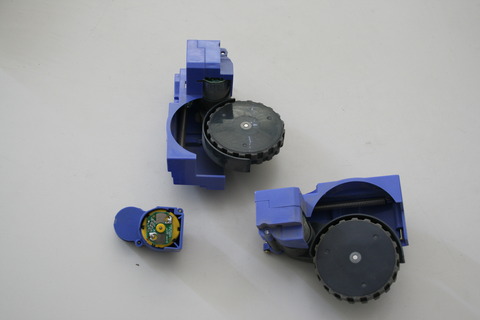
| + | Image:Roomba_12.JPG | Here you can see the three motor components removed from the robot's hull. The small one is dedicated to the rotating brush: it gets power from two spring-like contacts directly connected to the underside of the main circuit board, passing through a cutout in the upper shell of the robot. You can see springs in the picture, at the bottom of the motor enclosure. When the motor is in place, the springs touch two flat, metallic regions on a small PCB fitted to the back of it. | ||
| + | Image:Roomba_13.JPG | | ||
</gallery> | </gallery> | ||
Revision as of 16:24, 10 March 2010
This page is dedicated to the disassembly of a Roomba 560 vacuuming robot. Its purpose is to provide AIRLab users (or anyone else) wanting to hack a Roomba with a guide to the process, so that they can plan their work easily. Other Roomba 500-series models should be similar to the one featured in this page.
Please note that the robot we have taken apart was well-used, so you will see a fair bit of dust and dirt on the parts... all for the sake of realism. (Just joking: simply, that was a broken robot we could spare in case the process proved to be fatal :-) )
If you click on any of the images below, you will be taken to its own AIRWiki page, where you will be able to download the file. However, the files are NOT high-resolution (480x320 pixels: on this page they are shown at full resolution). You can download the high-resolution originals of the images (and some additional image not shown by this AIRWiki page) from here. Note that the originals are 3888x2592 pixels, and each of them weighs in at 3-5MB.
Before dissection
Here you can see the Roomba 560 before any disassembling occurred.
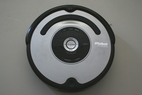
Top view. It shows the control panel and little more (on the top you can see the omnidirectional sensor and the bumper, but there's not much to note).
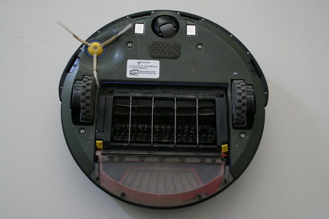
Bottom view. This is more interesting, as you can see (almost) all the moving parts, i.e., the two actuated wheels (bigger), the idler wheel (on top), the two rotating brushes, and the side brush used to catch dirt from corners. The "almost" is due to the fact that the Roomba also sports a small fan in the dust compartment (the only real vacuuming action occurs there) and a motor that lifts the whole brush module when the robot is on a carpet.
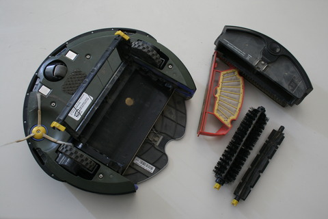
The removable elements of the Roomba: two rotating brushes and the dust compartment. The latter includes a small fan, which receives power from the two clamp-like contacts visible on the underside of the robot, and a red element (shown in its open position by the picture) supporting a dust filter.
Two other elements that are easily removed are the idler wheel assembly (wheel and socket, both removed by simply pulling) and the side brush (held in place by a screw).
Another view of the front wheel assembly, the side brush and the underside of the robot. At the bottom of the wheel socket you can see an emitter and a receiver, used to detect if the black/white wheel is actually rotating or is stuck.


Removing the bottom cover
To get to the electromechanical elements of the robot, you have to remove the bottom cover (as we will see later, electronics is accessed from the top instead).
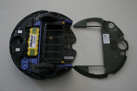
Four captive screws hold in place the bottom cover. Removing it exposes the battery and exposes some additional electromechanical systems (enclosed in blue plastic cases).
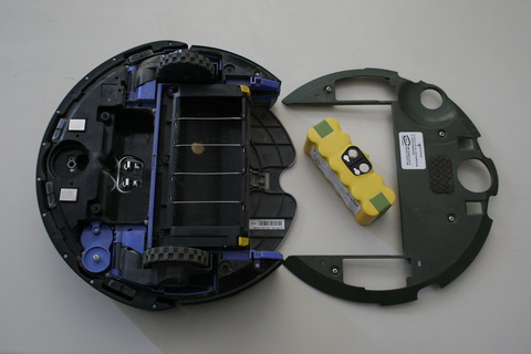
To remove the battery, simply pull it out using the lateral green (cloth) handles. The contacts on the battery are flat and, as we will see later on, touch small elastic plates directly fitted to the main circuit board. These plates pass through a cutout in the upper shell of the robot, and here are seen exposed.
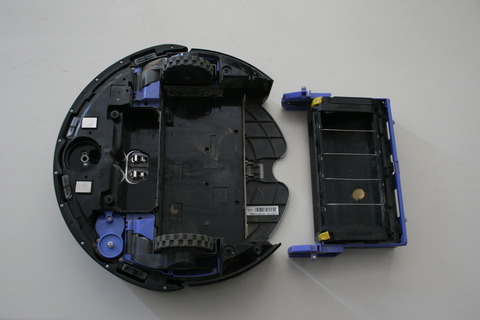
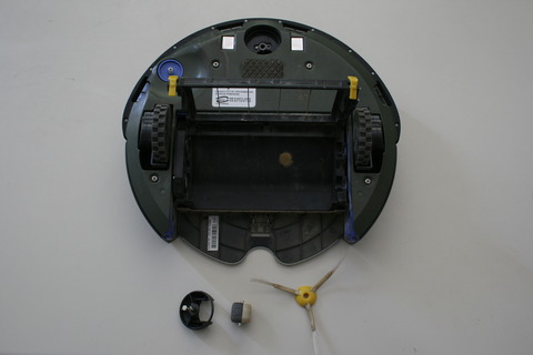
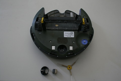
This is the robot with the brush housing removed. The gold-coloured, circular metal element at the bottom of the housing is most probably the "dirt detector" sensor that the robot uses to find out floor spots requiring particular attention.


The brush housing
This element is more complex than it is immediately apparent.

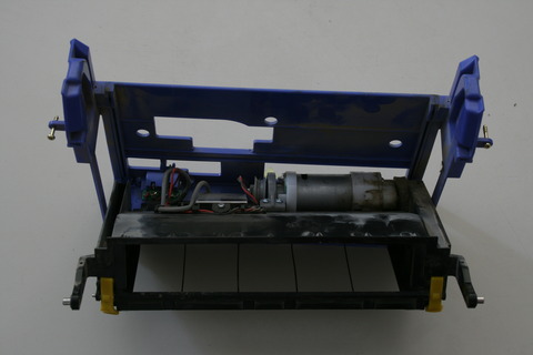
By separating the elements of the brush housing, its contents become visible. Separation is obtained by flexing the two plastic arms seen on the top of the image, so that the two metal pins at their extremities come out of the corresponding holes in the blue part of the housing. As such holes pass through the blue element, the flexing is easily done by inserting a tool from the other end of the hole.
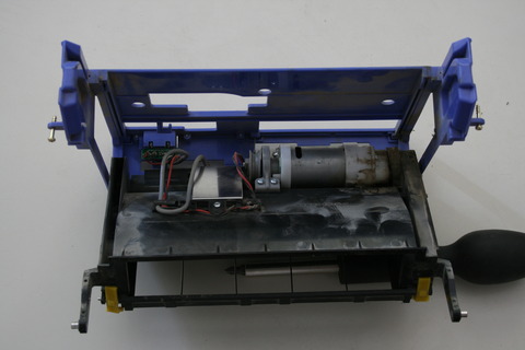
The housing two motors: one is used for brush rotation, while and the other lifts the whole brush higher from the ground when needed (e.g., the robot is on a thick carpet). The motors are mounted back-to-back: the brush motor is on the right. The right (thicker) wall of the black element is actually an enclosure housing the gear reduction for the brush motor. On the spindle of the lift motor is a grey pulley, on which a short string is wound when the brush housing is lifted from the ground. The string is terminated by a small brass cap passing through a hole in the blue part of the housing. This cap is (barely) visible at the bottom of the housing in the preceding picture.
Another view of the brush housing. The metal plate is the enclosure of the "dirt detector".


The active wheels
Roomba is propelled by two actuated wheels, in a classical differential drive configuration. By modulating the rotating speeds of each the wheels independently from the other, different trajectories are obtained.
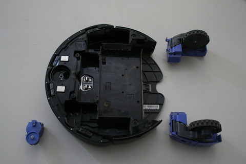
Here you can see the three motor components removed from the robot's hull. The small one is dedicated to the rotating brush: it gets power from two spring-like contacts directly connected to the underside of the main circuit board, passing through a cutout in the upper shell of the robot. You can see springs in the picture, at the bottom of the motor enclosure. When the motor is in place, the springs touch two flat, metallic regions on a small PCB fitted to the back of it.