Difference between revisions of "Disassembling a Roomba 560"
| Line 80: | Line 80: | ||
Image:Roomba_37.JPG | This is the other part of the PCB, where the only notable element is the main processor. | Image:Roomba_37.JPG | This is the other part of the PCB, where the only notable element is the main processor. | ||
Image:Roomba_36.JPG | A view of the auxiliary board, also showing the connections to the side of the main PCB on the back of the robot. From left to right you can see the following connections (now disconnected from the PCB): the speaker cable (yes, there is a speaker on the robot: it is used to ask for help in case of problems); the cable connecting the auxiliary PCB to the main one; the power connections to the dust tray, where there is a small fan; and the connections to the power connector on the side of the robot, used for the battery charger. | Image:Roomba_36.JPG | A view of the auxiliary board, also showing the connections to the side of the main PCB on the back of the robot. From left to right you can see the following connections (now disconnected from the PCB): the speaker cable (yes, there is a speaker on the robot: it is used to ask for help in case of problems); the cable connecting the auxiliary PCB to the main one; the power connections to the dust tray, where there is a small fan; and the connections to the power connector on the side of the robot, used for the battery charger. | ||
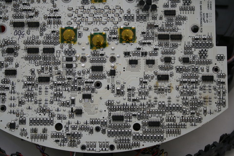
| − | Image:Roomba_38.JPG | The upper side of the main board, where most of the components are mounted. The gold discs are pushbuttons; the strange array of SMD leds that is visible just above of the lower three buttons is the 7-segment display used for user scheduling of robot tasks | + | Image:Roomba_38.JPG | The upper side of the main board, where most of the components are mounted. The gold discs are pushbuttons; the strange array of SMD leds that is visible just above of the lower three buttons is the 7-segment display used for user scheduling of robot tasks. On top left you can see a connector, presumably (until we perform some tests on the signals...) used for serial communications. The following pictures will be closeups of the different areas of the board. |
| − | Image: | + | Image:Roomba_40.JPG | Top left area. |
| − | Image: | + | Image:Roomba_39.JPG | Top right area. The small green daughterboard on the right is a radio communication module based on the Zigbee protocol, used by the robot to communicate with its accessories. The board is based on [http://www.freescale.com/files/rf_if/doc/data_sheet/MC13202.pdf?pspll=1 this IC]. |
Image:Roomba_41.JPG | Bottom left area. | Image:Roomba_41.JPG | Bottom left area. | ||
Image:Roomba_42.JPG | Bottom right area. | Image:Roomba_42.JPG | Bottom right area. | ||
Image:Roomba_43.JPG | Side view, showing the speaker (the black round element on the right, integrated into the side of the robot). | Image:Roomba_43.JPG | Side view, showing the speaker (the black round element on the right, integrated into the side of the robot). | ||
</gallery> | </gallery> | ||
Revision as of 12:08, 11 March 2010
The Roomba by Irobot is a vacuuming robot; but it is also one of the (still) few examples of mass-market robotic products. Its low cost, the easy availability of spare parts and the wide diffusion make the Roomba an interesting starting point for "hacking".
This page is dedicated to the disassembly of a Roomba 560. Its purpose is to provide AIRLab users (or anyone else) wanting to hack a Roomba with a guide to the process, so that they can plan their work easily. Other Roomba 500-series models should be similar to the one featured in this page.
Please note that the robot we have taken apart was well-used, so you will see a fair bit of dust and dirt on the parts... all for the sake of realism. (Just joking: simply, that was a broken robot we could spare in case the process proved to be fatal :-) )
If you click on any of the images below, you will be taken to its own AIRWiki page, where you will be able to download the file. However, the files are NOT high-resolution (480x320 pixels: on this page they are shown at full resolution). You can download the high-resolution originals of the images (and some additional image not shown by this AIRWiki page) from here. Note that the originals are 3888x2592 pixels, and each of them weighs in at 3-5MB.
Contents
Before the dissection
Here you can see the Roomba 560 before any disassembling occurred.
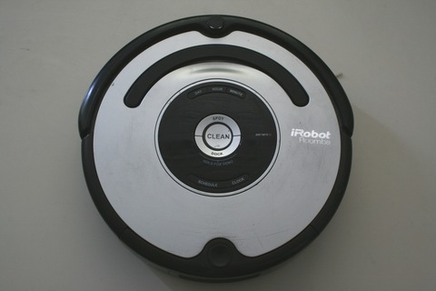
Top view. It shows the control panel and little more (on the top you can see the omnidirectional sensor and the bumper, but there's not much to note).
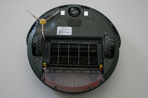
Bottom view. This is more interesting, as you can see (almost) all the moving parts, i.e., the two actuated wheels (bigger), the idler wheel (on top), the two rotating brushes, and the side brush used to catch dirt from corners. The "almost" is due to the fact that the Roomba also sports a small fan in the dust compartment (the only real vacuuming action occurs there) and a motor that lifts the whole brush module when the robot is on a carpet.
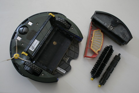
The removable elements of the Roomba: two rotating brushes and the dust compartment. The latter includes a small fan, which receives power from the two clamp-like contacts visible on the underside of the robot, and a red element (shown in its open position by the picture) supporting a dust filter.
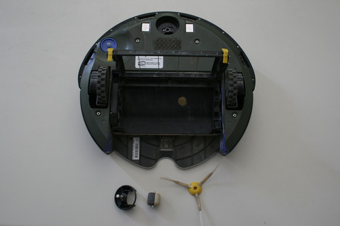
Two other elements that are easily removed are the idler wheel assembly (wheel and socket, both removed by simply pulling) and the side brush (held in place by a screw). The two square metal plates at the side of the idler wheel mounting place are the contacts used to power the robot when it is on its recharge base.
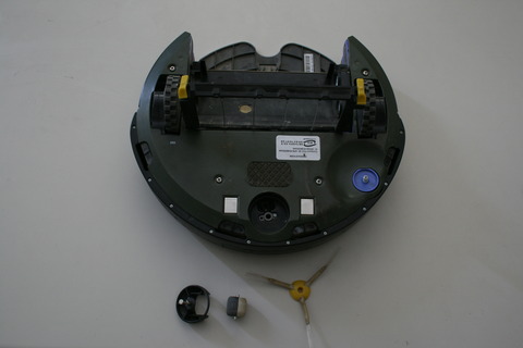
Another view of the front wheel assembly, the side brush and the underside of the robot. At the bottom of the wheel socket you can see an emitter and a receiver, used to detect if the black/white wheel is actually rotating or is stuck.


Removing the bottom cover
To get to the electromechanical elements of the robot, you have to remove the bottom cover (as we will see later, electronics is accessed from the top instead).
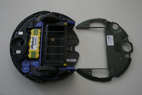
Four captive screws hold in place the bottom cover. Removing it exposes the battery and exposes some additional electromechanical systems (enclosed in blue plastic cases).
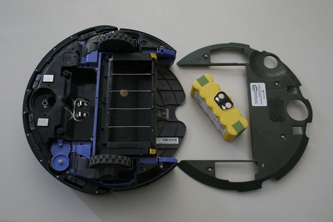
To remove the battery, simply pull it out using the lateral green (cloth) handles. The contacts on the battery are flat and, as we will see later on, touch small elastic plates directly fitted to the main circuit board. These plates pass through a cutout in the upper shell of the robot, and here are seen exposed.
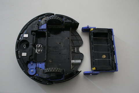
This is the robot with the brush housing removed. The gold-coloured, circular metal element at the bottom of the housing is most probably the "dirt detector" sensor that the robot uses to find out floor spots requiring particular attention.


The brush housing
This element is more complex than it is immediately apparent.

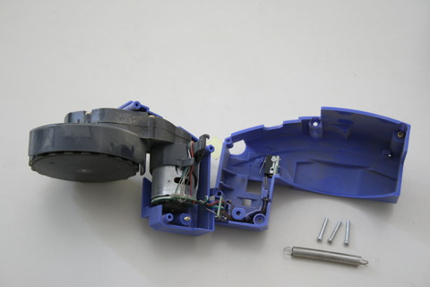
By separating the elements of the brush housing, its contents become visible. Separation is obtained by flexing the two plastic arms seen on the top of the image, so that the two metal pins at their extremities come out of the corresponding holes in the blue part of the housing. As such holes pass through the blue element, the flexing is easily done by inserting a tool from the other end of the hole.
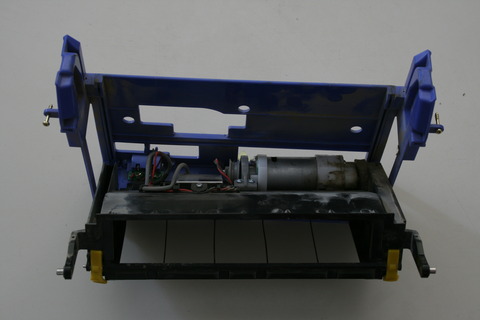
The housing two motors: one is used for brush rotation, while and the other lifts the whole brush higher from the ground when needed (e.g., the robot is on a thick carpet). The motors are mounted back-to-back: the brush motor is on the right. The right (thicker) wall of the black element is actually an enclosure housing the gear reduction for the brush motor. On the spindle of the lift motor is a grey pulley, on which a short string is wound when the brush housing is lifted from the ground. The string is terminated by a small brass cap passing through a hole in the blue part of the housing. This cap is (barely) visible at the bottom of the housing in the preceding picture.
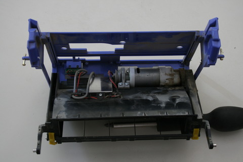
Another view of the brush housing. The metal plate is the enclosure of the "dirt detector".


The active wheels
Roomba is propelled by two actuated wheels, in a classical differential drive configuration. By modulating the rotating speeds of each the wheels independently from the other, different trajectories are obtained.
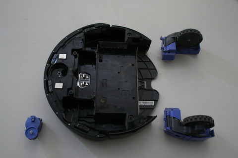
Here you can see the three motor components removed from the robot's hull. All of them are held in place by captive screws. The small motor is dedicated to the side brush: it gets power from two spring-like contacts directly connected to the underside of the main circuit board, passing through a cutout in the upper shell of the robot. You can see springs in the picture, at the bottom of the motor enclosure.
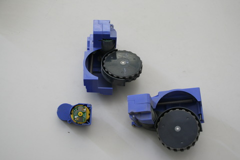
The wheel modules and the side brush motor. The latter is fitted with a small PCB (Printed Circuit Board) with two contact regions: when the motor is in place, the springs protruding from the top of the robot touch these regions and power the motor. The wheels are spring-loaded by the long spring visible in the picture, so that if the robot is lifted from the ground they are pulled away from the robot's body. A microswitch detects when this occurs, so that the robot can be stopped (for instance) if it is lifted from the ground.
Three (non captive, so watch out to avoid losing them!) screws have to be removed to open one of the wheel enclosures. Once open, you can see the motor and the microswitch. The thick black element connecting the wheel to the robot encloses the gear reduction. On the back of the robot is a dark grey disc; at first examination, it seems to be part of the wheel encoder system (presumably magnetic, to avoid problems with the high level of dust).


The front sensors
Most of the sensors of the Roomba are located on the front of the robot. Such sensors are:
- bumpers to detect collisions;
- two sets of infrared emitters/receivers: front-looking to detect the presence of obstacles, and downward-looking to detect the presence of the floor (so the robot is able to avoid falling down the stairs);
- an omnidirectional infrared sensor to detect the presence of active Roomba accessories such as "virtual walls" and recharge stations.
By removing the bottom part of the bumper (held in place by many non-captive screws), the bumper can be separated from the body of the robot.
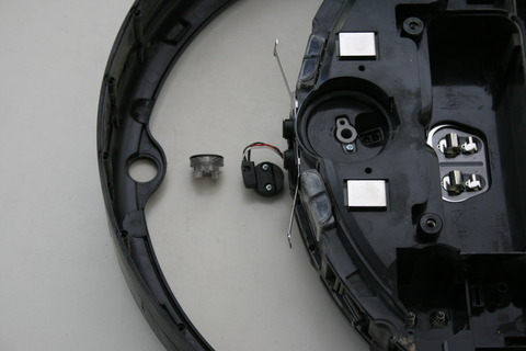
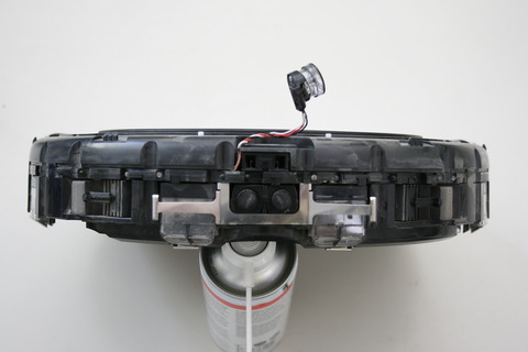
On the top of the bumper is fitted the omnidirectional sensor, composed of two parts: a conical mirror enclosed in clear plastic (this is the part of the sensor that -for an assembled robot- lies outside the bumper, on top of the robot), and a black base with the sensing element (which is hidden within the bumper). These parts are kept together by two screws: by removing them, they separate and are also free to be removed from the bumper.
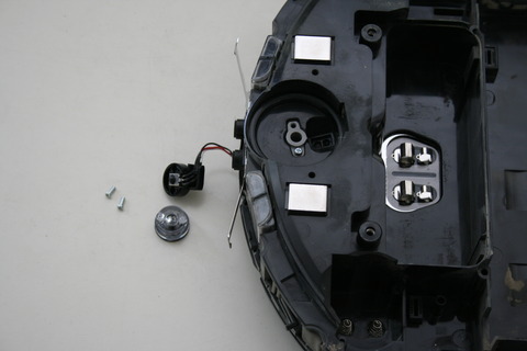
A view of the two elements of the omnidirectional sensor. The picture also shows two interesting features of the robot: the metal plate used to keep the center part of the bumper in place, and -at the very front of the robot- two black "buttons" about 10mm in diameter. These are loaded by stiff springs, and most probably are shock absorbers to avoid damage when the robot hits an obstacle.
Front view. Some of the elements shown are: the omnidirectional sensor, the metal plate, the front of the shock absorbers, (above these) the twin square openings of the forward-looking emitter/receiver couple (we will see that, unlike the other couples, this one is directly mounted on the main PCB), the left and right arms of the bumper switches (two black horizontal arms, about 25mm long, respectively at the immediate right and at the immediate left of the light grey rectangular strips; strips which, by the way, are made of foam and are probably used as lateral shock absorbers).
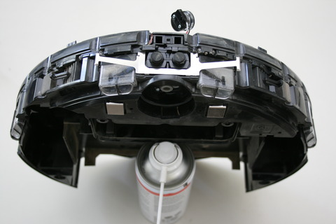
Another front view, where the downward-firing infrared emitter/receivers are especially evident: they are the four clear plastic elements, each of which has a roughly trapezoidal downward-looking side, subdivided in two by a central ridge. Two of them are at the very front of the robot, and two are in a more lateral position. Presumably, their active surface is not horizontal but instead tilted away from the robot to "see" some centimeters away and, thus, perceive if the robot is heading towards an area where the floor is missing before Roomba actually reaches it.


Removing the top shell
The upper part of the robot is a sort of tray, where the main circuit board (and a small auxiliary board as well) is enclosed. It is separated by the (dusty) bottom part of the robot's hull, except where cutouts are required to allow for the connections between the board and the electromechanical components. A metal shield is located on the bottom of the "tray", presumably to shield the data-processing parts of the circuit from interference from the motors below.
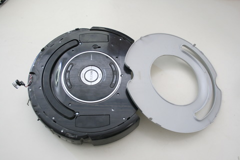
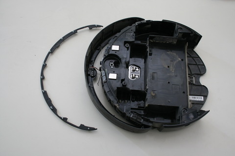
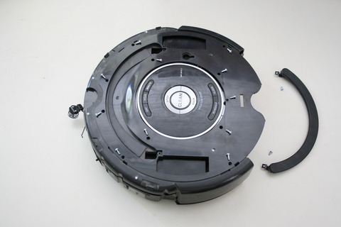
To reach the control board, the first thing to do is removing the upper cosmetic plate. This is a plastic plate in the form of a circle with a central, circular hole (seen here upside down). It is held in place by a few mechanical fixing points on the outside circumference (easily disengaged with a flat screwdriver) and a more resilient protrusion all around the border of the central hole. To remove the plate without breaking it, you have to disengage all the external fixing points and then insert a flat tool underneath the plate, gently forcing it up until the central fixing ring disengages. It feels very solid, but it is not glued in place!
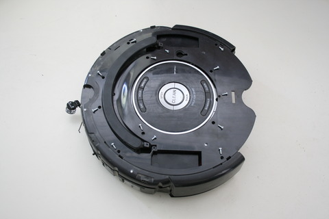
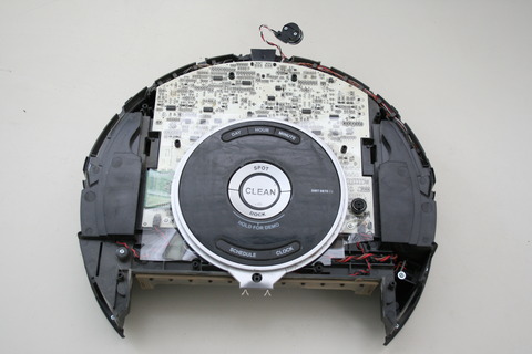
This is the top of the robot without the cosmetic plate. All the screws fixing the upper shell (the one covering the circuit boards) have been removed and point towards their sockets, including the two (smaller) screws which fix the handle in place.
Here, the handle has been removed: but you do not need to do it if you only want to remove the upper shell of the Roomba (the handle goes with it).
This is the robot without the upper shell. You can see the main PCB, partly covered by the control panel.
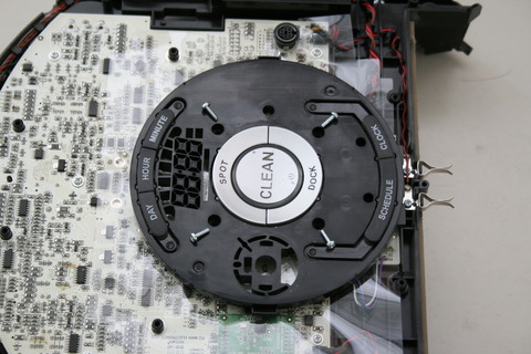
A closeup of the same configuration.
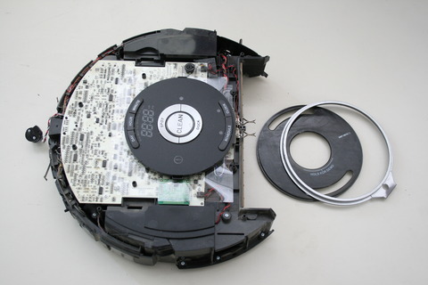
The outer, cosmetic plate covering the control panel is easily removed by lifting, along with its outer plastic ring.
Removing the flat black mask covering the structure of the control panel.
This is the structure of the control panel. It is held in place by four (non-captive) screws.
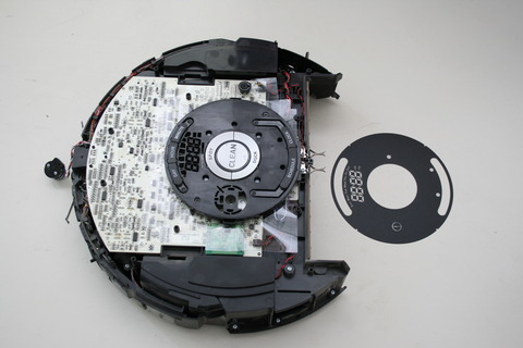
And finally... this is the upper side of the robot after the control panel has been fully removed. Note the clear plastic sheet on the right of the robot: it is placed between panel and PCB, and is easily lost as it's transparent...


The control board
The Roomba 560 includes two circuit boards: a main PCB and a small, secondary one. The second one is only used to add two pushbuttons to the control panel of the robot, while the first PCB -mostly populated by SMD components- houses all the circuitry of the robot. Data processing, control and power driving of the robot are all done by this board.
The main PCB is affixed to the robot's hull by small screws. Unscrewing these leaves the PCB loose but still attached to the sensors through a set of cables. As shown in the picture, beneath the PCB is a metal screen covered by a transparent sheet (be careful not to lose it, and be sure to have replaced it before powering up the robot!). The three black, rectangular protrusions on the underside of the board are the connectors used to power the wheel motors and the brush motor. The side brush motor is powered through the two spring contacts visible on the side of the board, while the central black area houses the metal plates which connect to the battery pack.
A closer view of the cables connecting the main PCB to the sensors. The black rectangular protrusion below the PCB is the housing of the front-looking emitter/receiver couple, directly soldered on the PCB (all the other couples are composed, instead, of discrete components housed in a curved plastic element (mounted on the front part of the robot) and connected to the PCB by cables).
A front view of the Roomba, with the PCB partially lifted from its place.
Another front view, from a slightly different viewpoint.
By gently pulling, the plastic element supporting the discrete IR emitters and receivers used by the robot as obstacle detectors can be removed. It is visible on the left of the picture, still connected to the PCB. The latter has been extracted from its housing in the upper shell of the robot; on the right is visible the clear plastic sheet that insulates the lower side of the PCB from the metal shield.
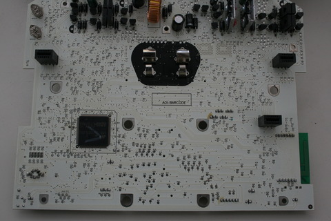
A full view of the underside of the main board. The following pictures will show this in more detail.
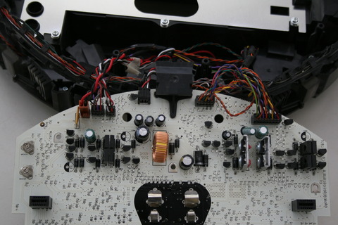
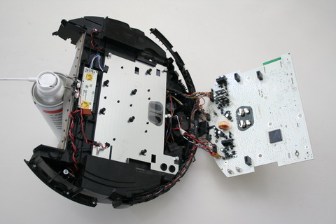
The part of the board next to the connections to the sensors houses the power components.
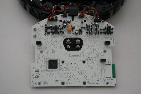
This is the other part of the PCB, where the only notable element is the main processor.
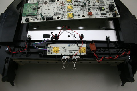
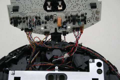
A view of the auxiliary board, also showing the connections to the side of the main PCB on the back of the robot. From left to right you can see the following connections (now disconnected from the PCB): the speaker cable (yes, there is a speaker on the robot: it is used to ask for help in case of problems); the cable connecting the auxiliary PCB to the main one; the power connections to the dust tray, where there is a small fan; and the connections to the power connector on the side of the robot, used for the battery charger.
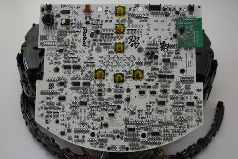
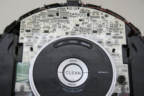
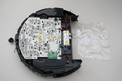
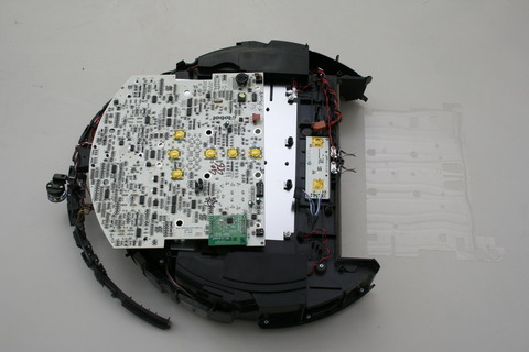
The upper side of the main board, where most of the components are mounted. The gold discs are pushbuttons; the strange array of SMD leds that is visible just above of the lower three buttons is the 7-segment display used for user scheduling of robot tasks. On top left you can see a connector, presumably (until we perform some tests on the signals...) used for serial communications. The following pictures will be closeups of the different areas of the board.
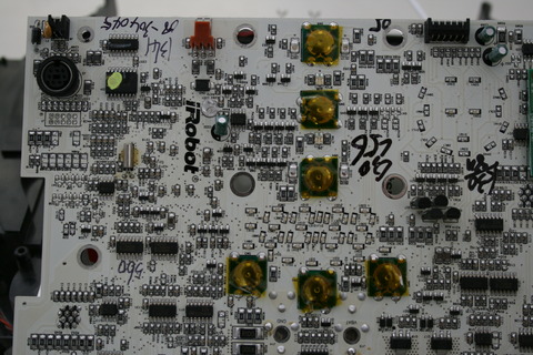
Top left area.
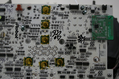
Top right area. The small green daughterboard on the right is a radio communication module based on the Zigbee protocol, used by the robot to communicate with its accessories. The board is based on this IC.
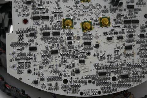
Bottom left area.
Bottom right area.
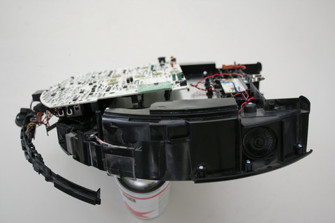
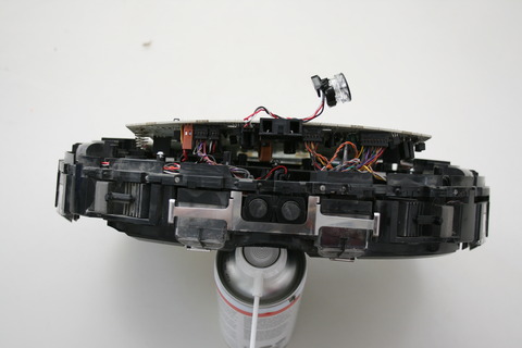
Side view, showing the speaker (the black round element on the right, integrated into the side of the robot).


