Difference between revisions of "Zoidberg II, powering robot fish"
MarcoPerri (Talk | contribs) (→Dates) |
MarcoPerri (Talk | contribs) (→Part 2: project description) |
||
| Line 43: | Line 43: | ||
== '''Part 2: project description''' == | == '''Part 2: project description''' == | ||
| − | The project is composed by: | + | The project is composed by: |
| − | State of the art; | + | * State of the art; |
| − | Preliminary studies and sketches; | + | * Preliminary studies and sketches; |
| − | Design notes and guidelines; | + | * Design notes and guidelines; |
| − | Description and results of experiments; | + | * Description and results of experiments; |
| + | * Useful internet links: [http://en.wikipedia.org/wiki/Doctor_Zoidberg Dr. Zoidberg] | ||
| + | |||
| + | |||
| + | === State of the art === | ||
| + | The work that mostly influenced the design of our robot is a lower-scale automaton realized by Shuxiang Guo, Yuya Okuda and Kinji Asaka, which is actuated with the same type of polymer that we used. | ||
| + | |||
| + | It is discussed in: | ||
| + | [[media:FishrobotICPF.pdf | ICPF Actuator-based Novel Type of Underwater Micro Biped Robot with Multi DOF]] | ||
| + | |||
| + | === Preliminary part design === | ||
| + | |||
| + | ==== Mechanical structure ==== | ||
| + | The design of the body has evolved into the current shape through many development steps, in response to the varying specifications of the on-board electronics, to changes in the manufacturing process of the hull, and for a better approach to the hydrostatic balance problem. | ||
| + | |||
| + | The first two images below represents the early proposed mostly flat design, and a step of the manufacturing of a "master" hull component in a modeling clay. The third image shows a simple prototype made of polyurethane foam, tethered to the tank for power supply. It can be noted the original configuration of the tail components, which were mounted in a horizontal fin arrangement with two parallel actuators. | ||
| + | |||
| + | <gallery> | ||
| + | Image:Test_forma_1.png|First test body shape | ||
| + | Image:Test_PLUS.jpg|Developed test body | ||
| + | Image:Test_propulsion.png|Propulsion test | ||
| + | </gallery> | ||
| + | |||
| + | ==== Electronics ==== | ||
| + | |||
| + | The first version of the on-board electronics was a two-boards arrangement. Due to problems and delays with the company responsible of the manufacturing of said boards, there are no working exemplars of this solution. In the meantime the circuit has been redesigned and simplified to fit a single board, and we put together a very simple intermittent circuit to carry the first autonomous tests (without the robot being tethered to the tank). | ||
| + | |||
| + | Below are shown, in order: the original schematics of the two boards, the schematic of the oscillator used for the first tests, based on a 555 chip, and the intermittent circuit assembled on a prototype board. | ||
| + | |||
| + | <gallery> | ||
| + | Image:Schema_1.png|First board schematic | ||
| + | Image:Schema_2.png|Second board schematic | ||
| + | Image:BasicOscillator.svg|Test circuit (simplified) schematic | ||
| + | Image:Test_circuit.jpg|Test circuit | ||
| + | </gallery> | ||
| + | |||
| + | ==== Videos of the actuator tests ==== | ||
| + | |||
| + | Here are some clips, filmed during the first experiments trying to have a working actuator. The polymer and the electrodes are held in place by rough adhesive, and the power is supplied by an external generator. we are manually changing the polarity of the current going through the actuator. | ||
| + | |||
| + | {{#ev:youtube|kDF3zGa5b-c}} | ||
| + | *[http://it.youtube.com/watch?v=kDF3zGa5b-c External link] | ||
| + | |||
| + | {{#ev:youtube|xNAmuwDQzKU}} | ||
| + | *[http://it.youtube.com/watch?v=xNAmuwDQzKU External link] | ||
| + | |||
| + | === Final design === | ||
| + | (todo) | ||
| + | <gallery> | ||
| + | Image:FishBoard.svg|Final review board schematic | ||
| + | Image:Zoidberg_interno.jpg|The hull open, exposing the wiring | ||
| + | Image:Zoidberg_incapsulamento.jpg|Internal arrangement of the structure | ||
| + | </gallery> | ||
| + | <gallery> | ||
| + | Image:PesceUpWeb.png|Complete robot, top view | ||
| + | Image:PesceSideWeb.png|Complete robot, side view | ||
| + | </gallery> | ||
| + | |||
| + | === Tests and results === | ||
| + | (todo) | ||
| + | |||
| + | ==== Videos of the robot in action ==== | ||
| + | |||
| + | {{#ev:youtube|_L9oLe1OXiU}} | ||
| + | *[http://it.youtube.com/watch?v=_L9oLe1OXiU External link] | ||
| + | |||
| + | {{#ev:youtube|ptSdlPzTORw}} | ||
| + | *[http://it.youtube.com/watch?v=ptSdlPzTORw External link] | ||
Revision as of 17:15, 28 October 2009
Part 1: project profile
Project name
Zoidberg II, powering robot fish
Project short description
This project is aimed at designing, constructing and improving autonomous robot fish, starting from the ZOIDBERG project. It will be able to swim deeply in the water, to communicate and to orient in a free space thanks to several sensors mounted on-board.
Dates
Start date: 2008/11/01
End date: 2009/12/23
People involved
Project head(s)
Prof. Gini Giuseppina - User:GiuseppinaGini
Other Politecnico di Milano people
Ing. Paolo Belluco - User:PaoloBelluco
Students currently working on the project
Andrea Parolina - User:AndreaParolina
Dario Simontacchi - User:DarioSimontacchi
Marco Perri - User:MarcoPerri
Students who worked on the project in the past
Francesco Milli - User:FrancescoMilli
Maurizio Mercurio - User:MaurizioMercurio
Alessandro Nava - User:AlessandroNava
Laboratory work and risk analysis
Laboratory work for this project will be mainly performed at AIRLab/Lambrate. It will include significant amounts of mechanical work as well as of electrical and electronic activity. Potentially risky activities are the following:
Use of mechanical tools. Standard safety measures described in Safety norms will be followed. Use of soldering iron. Standard safety measures described in Safety norms will be followed. Use of high-voltage circuits. Special gloves and a current limiter will be used. Robot testing. Standard safety measures described in Safety norms will be followed.
Part 2: project description
The project is composed by:
- State of the art;
- Preliminary studies and sketches;
- Design notes and guidelines;
- Description and results of experiments;
- Useful internet links: Dr. Zoidberg
State of the art
The work that mostly influenced the design of our robot is a lower-scale automaton realized by Shuxiang Guo, Yuya Okuda and Kinji Asaka, which is actuated with the same type of polymer that we used.
It is discussed in: ICPF Actuator-based Novel Type of Underwater Micro Biped Robot with Multi DOF
Preliminary part design
Mechanical structure
The design of the body has evolved into the current shape through many development steps, in response to the varying specifications of the on-board electronics, to changes in the manufacturing process of the hull, and for a better approach to the hydrostatic balance problem.
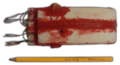
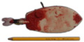
The first two images below represents the early proposed mostly flat design, and a step of the manufacturing of a "master" hull component in a modeling clay. The third image shows a simple prototype made of polyurethane foam, tethered to the tank for power supply. It can be noted the original configuration of the tail components, which were mounted in a horizontal fin arrangement with two parallel actuators.
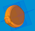
First test body shape
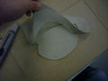
Developed test body
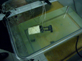
Propulsion test


Electronics
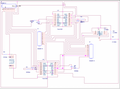
The first version of the on-board electronics was a two-boards arrangement. Due to problems and delays with the company responsible of the manufacturing of said boards, there are no working exemplars of this solution. In the meantime the circuit has been redesigned and simplified to fit a single board, and we put together a very simple intermittent circuit to carry the first autonomous tests (without the robot being tethered to the tank).
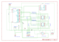
Below are shown, in order: the original schematics of the two boards, the schematic of the oscillator used for the first tests, based on a 555 chip, and the intermittent circuit assembled on a prototype board.
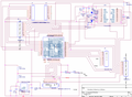
First board schematic
Second board schematic
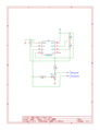
Test circuit (simplified) schematic
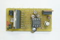
Test circuit


Videos of the actuator tests
Here are some clips, filmed during the first experiments trying to have a working actuator. The polymer and the electrodes are held in place by rough adhesive, and the power is supplied by an external generator. we are manually changing the polarity of the current going through the actuator.
Final design
(todo)
Final review board schematic
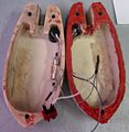
The hull open, exposing the wiring
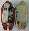
Internal arrangement of the structure


Complete robot, top view
Complete robot, side view


Tests and results
(todo)