Difference between revisions of "VCSBC4018 vision board"
From AIRWiki
| Line 10: | Line 10: | ||
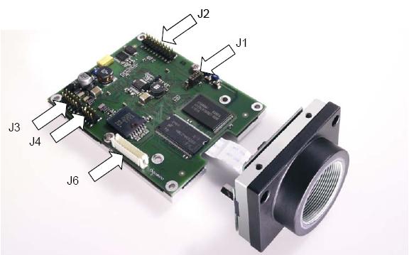
The photo above represent a generic board, in fact the VCSBC4018 doesn't have the J6 jumper. | The photo above represent a generic board, in fact the VCSBC4018 doesn't have the J6 jumper. | ||
| + | |||
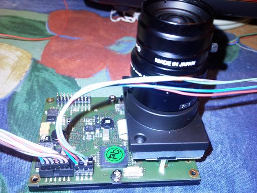
The photo below shows the realy board with the two jumpers connected. | The photo below shows the realy board with the two jumpers connected. | ||
| + | |||
[[Image:Collegamenti on board.jpg]] | [[Image:Collegamenti on board.jpg]] | ||
Revision as of 17:43, 17 July 2010
This tutorial will explain how to use the camera board VCSBC4018.
This camera board mount with a TMS320C64xx working at 40MHZ. The camera sensor can take images with a resolution of 640 x 480 pixels. The board is equiped with a 100 Mbit Ethernet that allow to comunicate with a PC, 32 MB RAM and 4 MB flash EPROM. Power supply: 12~14V.
Part 1: HW connection
First of all it's needed to connect the LAN jumper (J4) and power jumper (J3).

The photo above represent a generic board, in fact the VCSBC4018 doesn't have the J6 jumper.
The photo below shows the realy board with the two jumpers connected.
