Difference between revisions of "Talk:Graphical user interface for an autonomous wheelchair"
(→To Do) |
|||
| Line 8: | Line 8: | ||
===To Do=== | ===To Do=== | ||
| − | |||
| − | |||
| − | |||
| − | |||
| − | |||
| − | |||
==Map representation== | ==Map representation== | ||
Revision as of 09:58, 11 May 2009
Contents
General
The interface is used mainly to drive the Lurch wheelchair. It has different screens, corresponding to the different rooms or different environments where the wheelchair can move. The screens are organized hierarchically: a main screen permits to choose whether to drive the wheelchair or perform other tasks. The screens used for driving the wheelchair show a map of the environment, with different levels of details; e.g., a map might show just the rooms of a house, and then another map might show the living room with the furniture and ‘interesting’ positions (like near the table, in front of the TV, beside the window...).
The interface should be as accessible as possible. It can be driven by a BCI, used with the touch screen or with the keyboard. The BCI is based on the P300 and ErrP potentials; so the interface should highlight the possible choices on at a time (in orthogonal groups if the choices are numerous), and show the choice detected by the BCI for ErrP-based confirmation.
Maybe the screen should be updated while the wheelchair navigates; e.g., when the wheelchair enter into the kitchen, the GUI shows the map of the kitchen.
To Do
Map representation
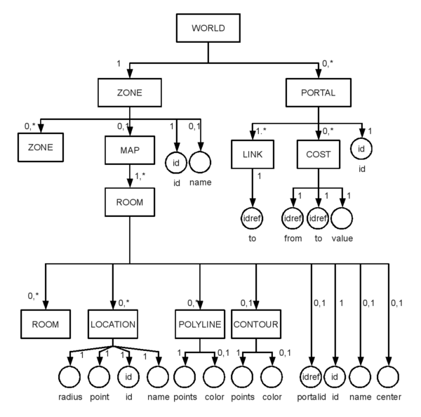
link to OpenOffice Draw source media:Lurch_map_xml_structure.odg.zip
link to a simple example media:Lurch_map_xml_example.xml.zip complete this example, it's very minimal
- If there is no map in a zone, the interface will show only the names of the the possible destinations (i.e., zones). If there is a map, zones are drawn as polygons ().
- If anything has no NAME, the ID is used instead.
- Costs for a portal are 1 by default; forbidden connections have infinite cost.
- Rooms that are portals have no destinations and no inner rooms.
- Colors currently are not saved by the cad and are not read by the bci gui.
Communication Protocol Requirements
- Cross-platform (at least Linux and Windows)
- Based on the IP protocol
- Asynchronous (as much as possible), so as not to block remote processes
- Preferably, the protocol should be in ASCII, with fixed-width fields (the number of fields is variable, by necessity).
To Do
- List of the pieces of information to be transferred between the application and the GUI
Communication Protocol
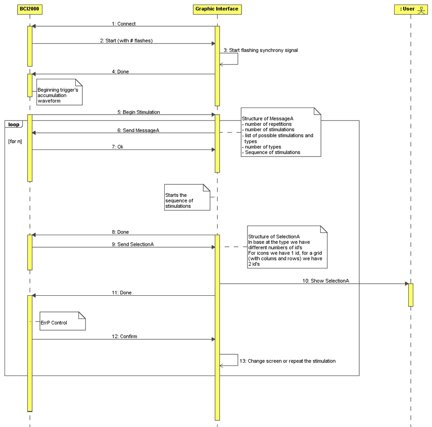
UML Sequence Diagram
Diagram
Comments about the diagram
Structure of MessageA:
- Number of repetitions: number of flashings
- Number of stimulations: number of flashings in one repetition
- List of the stimulations: list of the possible stimulations with its type
- Number of types
- Stimulations sequence: it includes all the repetitions
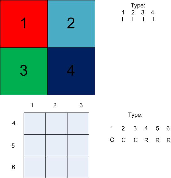
Each stimulation must hav associated a type (e.g Icon, Row-Column)
Structure of SelectionA:
- For each number of stimulation types you have a equal number of ids (e.g for Icon it will be used 1 id, for Row-Column 2 ids)
Graphic example of id:
It will be also an end asynchronous message, that brings the BCI in pause, and it closes the graphic interface.
If the syncrony will be lost there's a Reset Message that restarts from the calibration. It will be activated when the number of the classifications is different from the number of the stimulations on the screen
Implementation of GUI
Primo incontro (04/03/2009)
- Attualmente sulla carrozzella è installata una GUI molto semplice, che lavora all'interno del sistema BCI2000. L'idea è quella di creare una interfaccia asincrona che dovrà interagire con il sistema BCI2000 già realizzato mediante un socket TCP.
- Ci sono diverse possibilità per implementare la GUI:
0) Stimoliamo le singole location presenti all'interno della mappa: il problema è che può diventare pesante, e che può essere difficile dal punto di vista cognitivo per l'utente.
1) Per prima cosa stimoliamo i diversi locali, e poi stimoliamo le location appartenenti al singolo locale selezionato (in realtà dovremo continuare a stimolare anche gli altri locali, nel caso in cui l'utente volesse uscire dalla stanza!) Le singole location possono essere stimolate in diversi modi: per gruppi, singolarmente, tramite una griglia.
2) Dividiamo la piantina in celle e poi le stimoliamo singolarmente. Questo approccio può essere problematico dal punto di vista della pianificazione del percorso: come fare se la location non è direttamente raggiungibile dall'interno della singola cella, per esempio a causa della presenza di un muro?
L'approccio 1) è decisamente il più naturale. Si può comunque pensare di sviluppare tutti i metodi e poi confrontarli.
- Le caratteristiche della GUI devono essere:
- menu gerarchico per la navigazione
- file di configurazione (direttamente lo stesso file del pianificatore) deve definire la piantina, le stanze, le location, (gruppi di location?).
- Il linguaggio in cui sviluppare la GUI può essere
- MAIA forte rischio di avere problemi di sincronizzazione!
- SDL su C++. Optiamo per questa scelta, che presenta meno rischi.
- FATTO (disponibile su airBAT)
- interfaccia grafica con due quadrati che si illuminano in modo sincronizzato tra loro.
- interfaccia grafica con una semplice mappa, i cui ambienti si illuminano in maniera randomica. Da notare che le librerie usate sono SDL.h e SDL_image.h (quest'ultima è stata introdotta al momento della creazione delle stanze da illuminare e non nella precedente versione con i quadrati che si illuminano in modo sincrono)
Secondo incontro (19/03/2009)
- I sorgenti realizzati sono stati provati sulla carrozzina e funzionano correttamente. Il monitor non deve essere settato ad un livello troppo luminoso, altrimenti i fotodiodi vanno in saturazione.
- Problema delle mappe: bisogna decidere come descrivere i vari ambienti della mappa. L'idea è quella di usare dei punti e delle rette. Inoltre il metodo che verrà deciso per la GUI dovrà essere lo stesso che utilizzerà anche il pianificatore. Eventualmente il metodo può essere generalizzabile per una qualsiasi mappa caricata.
- FATTO (disponibile su airBAT)
- estensione della precedente interfaccia grafica, realizzata utilizzando le librerie SDL_gfx. In questo modo è stato possibile "esternalizzare" il disegno delle primitive geometriche, rendendo più semplice l'individuazione dei poligoni di illuminazione delle varie stanze a partire dagli spigoli delle stanze stesse.
Terzo incontro (09/04/2009)
- Il presente incontro è stato interamente dedicato alla discussione e formalizzazione di uno schema comune di descrizione delle mappe. Il modello (la cui descrizione è visibile nella sezione 'Map representation') verrà utilizzato sia da coloro che realizzeranno l'interfaccia grafica, sia da coloro che dovranno migliorare il pianificatore attualmente funzionante sulla carrozzina.
- Si è deciso di utilizzare un modello basato sul linguaggio XML, grazie alle sue caratteristiche di flessibilità e semplicità.
- Per quello che riguarda la GUI, alcune parti (scelta della zona, del piano...) saranno realizzate mediante l'illuminazione di scritte, mentre altre parti (scegliere la singola stanza o la singola location all'interno della stanza) mediante l'illuminazione della mappa vera e propria.
- SVILUPPI FUTURI
- utilizzo di "portali" per il passaggio diretto tra luoghi diversi, anche a diversi livelli dell'albero XML. Al momento attuale, ci si potrà spostare di un solo livello per volta.
- studio dei diversi colori da utilizzare nell'interfaccia grafica
- DA FARE
- realizzazione di un parser xml mediante l'utilizzo delle librerie libxml2
- realizzazione delle parti riguardanti le zone e i piani (illuminazione di scritte) e le locations.
- generalizzazione del codice finora implementato


