Electroencephalographs
Contents
BeLight
A brief description of EbNeuro BeLight should go here.
Connectors
- 1-21: EEG inputs
- A, B, C, D Bipolar inputs
- NE: EEG reference
- ISOGN: EEG ground (Isolated ground)
- 22-24: Poly channels
- NEP: Poly reference
Booking
In order to book the electroencephalograph, please go to the IITLab page, where you can update a table with your new bookings.
Electrodes
There are two types of electrodes: electrodes pre-mounted on caps, and single electrodes. They are very simple, but as they are very important for the quality of the signal and are delicate (and also incredibly expensive, btw), please treat them carefully (avoid rattling them against each other, for example).
Maintenance
The paste or gel used during acquisitions must be thoroughly removed after use. Please follow the following procedure:
- Rinse the electrodes under running water. This step can remove only a part of the gel/paste. Please avoid washing or wetting the plugs.
- Put the electrodes in a container half-filled with water (there is a suitable container in the cabinet of the IITLab), so that the electrodes are completely submerged. Leave them there for some minutes, until all the gel/paste become dissolved. Change the water if it becomes too murky. Do not leave the electrodes underwater for too long.
- Rinse the electrodes under running water (and also rinse the container).
- Put the electrodes in a dry place, where they can dry up. You can accelerate this phase by first patting them with a towel. Again, make sure that plugs don't come in contact with water; if you hang a cap, make sure that water cannot drip along the cable onto the plug.
- Put the electrodes away in their bag in their box. Please make sure that they are absolutely dry before you put them away; the coating of electrodes is rather delicate.
Please take into account also the time for electrode cleaning when you plan your EEG acquisitions.
How to set up BCI instrumentation
You’ll nedd:
- Electroencephalograph (with PCMCIA connector)
- Laptop (ensures that the AC adapter is NOT connected, for safety reasons)
- Electrodes or an Electrodes Cap (designed for the 10-20 system)
- Conductive gel and/or abrasive electrode-gel
- Tape measure to put in the correct position the electrodes
- Adhesive tape (if using single electrodes to fix them)
- Syringe (if using electrodes cap, to insert the conductive gel into the electrodes hole)
- Fototransistor (if necessary)
Before starting, be sure that the Electroencephalograph AC adapter is far away from the patient because 50Hz can interfere and destroy EEG signal. Mobile phones can be another source of noise: it is better to switch them off before while performing the acquisition. In order to acquire the brain signal, it is possible to use an electrodes cap, or a set of separated single electrodes.
Electrodes Cap
Choose the suitable size for the patient, and then put the cap on his head in the correct position:
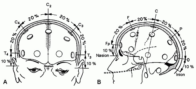
- measure his head size (from the nasion NS to the inion) this is the 100% of the measure
- now you can put the CZ electrode at 50% of the entire measure, and check the positions of the other electrodes (i.e. FP1 and FP2 should be at 10% of the measure from nasion) .
- fill in the electrodes with conductive gel (use the syringe), take care that hair don’t disturb the skin-electrode contact.
- remember to fill with condutictive gel also to electrodes cabled in red (NE=Neutral Electrode) and green (ISOGND=Isolated Ground) that are used respectively as reference (RF) and ground values in the measurements.
- connect the cable to the Electroencephalograph.
Separeted electrodes
If you haven’t got an electrodes cap you can position them one by one following this figure, with the relatives measures of each electrode:

Connect the reference electrode to the forehead and the GND electrode to the right earlobe.
Before connecting one electrode, put a little bit of abrasive gel on a cotton fioc and scratch the portion of patient’s skin where you’ll put the electrode.
Fill in the electrode with a little bit of conductive gel, and put it on the skin, in the correct position.
Fix the cable with adhesive tape, and connect it to the Electroencephalograph.
EOG
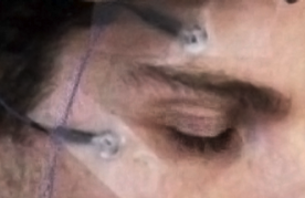
If you want to eliminate EOG artefacts from your data acquisitions, you would record EOG signal putting 2 more electrodes, near the patient eye. One electrode just over the eyebrow and one under the eye (REF) , like in the picture:

Connect the EOG cables to the A-Channel of the Electroencephalograph.
Impedance check
Now you can start Galileo Software and check if the correct values of impedance are measured. Click on the button “OHMMETER” in the upper toolbar, and the system will display the calculated value for each electrode, both in “graphical” form and in “numerical” one. Values under 10 KOhm are acceptable, values under 5 KOhm are very good. If your values aren’t under 10KOhm try to decrease them, filling the electrodes with more conductive gel until you reach acceptable values.
BCI2000 and Galileo
BCI2000 is a general-purpose software system for BCI research developed by the Wadsworth Center of the New York.
In our project BCI2000 is used for:
- data storage,
- stimulus presentation,
- on-line feedback applications.
Since our EEG amplifier is not directly supported by BCI2000, data acquisition is performed instead by Galileo that is the software provided with the EEG amplifier.
Galileo and BCI2000 communicate by means of two components:
- AirBat: a custom plugin for Galileo that sends the acquired data to GalileoSource through a pipe,
- GalileoSource: the data source seen by the other modules of BCI2000.
BCI2000 implements a client server architecture. When the server (operat) is launched it starts waiting for all the others modules to connect:
- the data source (in our case it is GalileoSource);
- the filter;
- the application.
When all these components are ready it is possible to start modifying the configuration parameters and finally run the application.
Note that GalileoSource will be ready only when the connection with AirBat is correctly established.
Thus the correct order in which the components should be launched is the following:
- start operat;
- start GalileoSource;
- start the filter component;
- start the application component;
- from Galileo start a new data acquisition with the AirBat plugin.
Presets in Galileo
Description of the presets saved in the Galileo software.
P300
Used for P300 and ErrP recordings. There are 4 EEG channels, 1 EOG, 2 external signals in DC; sampling frequency is 512 Hz.
- Channels and connectors
- EOG: EOG, input "A"; the "+" input for the electrode above the eye, the "-" input for the one below
- Fz: Fz, input 7
- Cz: Cz, input 12
- Pz: Pz, input 17
- Oz: Oz, input 20 (labeled as "O1" on the amplifier)
- Sync: phototransistor for stimulus synchronization; positive lead (red) in input 22, negative lead (black) in input NEP
- Button: button, used for target signaling; positive lead in input 23, negative lead in input NEP. If it's not used, please short the input 23 with NEP.
Links
- Brain-Computer Interface page on this Wiki
- EEG Montage for instructions on how to mount electrodes