LionHell McMillan
LionHell McMillan
| |
| Coordinator: | GiuseppinaGini (gini@elet.polimi.it) |
| Tutor: | |
| Collaborator: | |
| Students: | VittorioLumare (venom@venom.it) |
| Research Area: | Robotics |
| Research Topic: | Robot development |
| Start: | 2011/09/10 |
| End: | 2012/07/20 |
| Status: | Closed |
| Level: | Ms |
| Type: | Thesis |
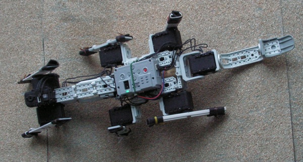
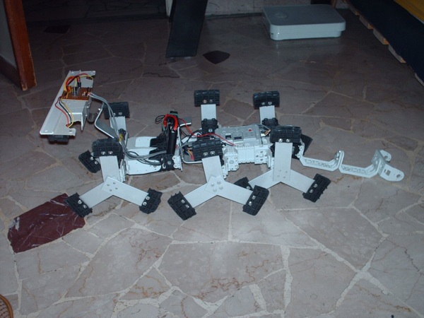
LionHell McMillan is an All Terrain Wheg Robot with Morphological Computation
It has been developed in a Master Thesis work in Robotics and Artificial Intelligence and it has been modified and improved in a Master Thesis work in Robotics and Artificial Intelligence by Alessandro Rosina ( http://airwiki.ws.dei.polimi.it/index.php/LionHell_McMillan_II ) , changing the name from "LionHell McMillan" to "LionHell McMillan II".
Info about Thesis
TItle : All Terrain Wheg Robot with Morphological Computation
Robot Name: LionHell McMillan
Correlator: Giuseppina Gini
Author: Vittorio Lumare
Area: Robotics and Artifical Intelligence
Start date: 2011/09/10
End date: 2012/07/24
Contents
The Idea
Starting Point
The new locomotion system called Wheg (Wheel + Leg) enable mobile robots to move on rough terrains, using a simple control system .
Objective
The project objective is to test the wheg system , in order to find a design (both of robot, both of whegs) able to give the best agility on rough natural terrains.
State of The Art
Simulations / Design
Simulation 1
The first robot model has been taken from an existent robot : EMBOT
This is a video of the first simulation with this model
As can be seen from simulation, robot model is unsuitable to the task.
The model has been then improved extending the body length of about 5 cm.
Simulation 2
Second simulation:
Now robot is able to climb all the steps, but this is not enough. The objective is harder: we want the robot to climb obstacles big as its body size, so I made another simulation with bigger obstacles:
Despite its longer body, the robot is unable to climb over the step.
This happens because it has no support in the back: when the back wheg (we see only one back wheg because of the 2D simulation) rotates, the mechanical support of the servomotor is the robot chassis, which starts rotating clockwise, making the robot falling backwards.
The solution to this problem is to avoid the chassis rotation.
How to avoid the chassis rotation?
A simple approach is to add a fixed link in the back , such a kind of tail, so that when the chassis starts rotating clockwise , the tail will touch the ground surface blocking the rotation.
Simulation 3
New Model:
- New central wheg
- New link added to body
- Joint in the body center
- Tail added to the back
- Wheg foot design improved to give better grip
As we can see , the robot is able to walk on very rough surface terrain.
He goes on even in presence of high surface spikes, thing that would have been not possible for the previous robot model.
This better behavior is principally due to the new central wheg added to the model, and to the slight body flexibility, due to the action of a spring and a damper in the body center.
Thanks to the tail action, robot never falls on his back.
The Real Robot
First Prototype
Final Prototype
Hardware
In this section all the hardware components will be illustrated, excluding structure because it was yet discussed in the previous chapters.
Servomotors
In this robot the servomotors are the only actuators.
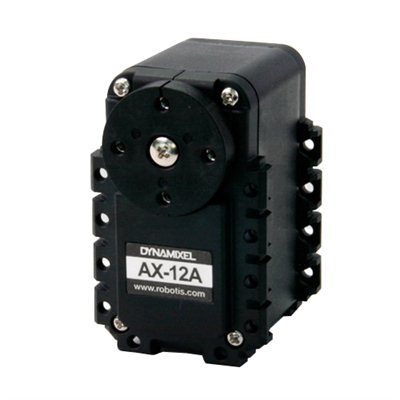
These servos have been taken from a Robotics kit called Bioloid, commercialized by Robotis.
The servomotor model is Dynamixel AX-12.
Dynamixel servos are very versatile, quite strong and can be used in two modes:
- Continuous Rotation mode
- Position mode
The only limit of these servos causing some problem in this work is a 60° dead-band . When motor shaft falls in this range, position is not retrievable from the internal potentiometer . This was a problem in continuous rotation mode, because I could not control the servo position in that range. This limit avoided me to synchronize all the six whegs to obtain a perfect control in climbing over obstacles. In fact I ended up with a simple open-loop motor control.
The other 3 servos were used in Position Mode:
- Two servos for the body joint in the center of robot
- One servo for the tail
Illustration 42: Servomotor - Dynamixel AX-12
Table 1: Servomotor - Dynamixel AX-12
In this case the dead band did not cause any problem, because a 180° movement was sufficient for the purpose.
I had to use two servos for the body joint, because of the high torque needed to move the head and the frontal pair of whegs. At a first time I tried to use one servo, but it was subject to overheating, until it burned. Using two servos in parallel, mechanically coupled, permitted a perfect control of the joint, without overheating.
Control Board
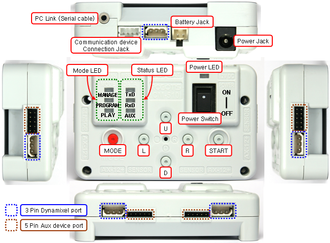
The central processing unit used is a CM-510.
It’s a development board producted by Robotis, and its fully compatible with Dynamixel AX-12 servos.
CM-510

Weight 51.3g
Controller ATMega2561
Working Voltage
 Allowed Range : 6.5V ~ 15V
 Recommended Voltage : 11.1V (Li-PO 3cell)
Consumed Current
 When IDLE : 50mA
 External I/O Maximum Current : 0.9A
 Total Maximum Current : 10A (Fuse)
Table 2: Control Board – CM-510
Illustration 43: Control Board - CM-510
This board is featured with standard Dynamixel ports, plus 6 other general purpose
ports.
Each general purpose port is featured with 4 usable pins:
- Ground
- Power (5V)
- Digital I/O
- Analogue Input (0V– 5V)
I used these ports to connect all peripheral sensors.
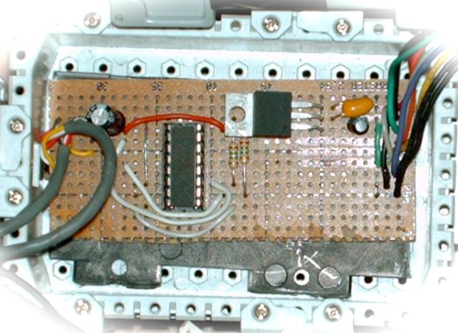
Since I had too many sensors for the available ports, I had to built two multiplexer boards:
- One board to multiplex 4 rangefinders
- One board to multiple 3-axis accelerometer
The boards inputs have not been fully used, so there are available channels for an eventual future use.
Sensors
The most critical aspects of perception in this robot are:
- Terrain sensing.
- Robot inclination with respect to gravity force vector.
Multiplexer Boards
I designed and builded two multiplexer boards: one for the IR-rangefinders , one for the 3-axsis-accelerometer.
The board below multiplexes the analog signal from each of the four used IR Sharp Rangefinders, in order to use a single analog input on the CM-510 Board.
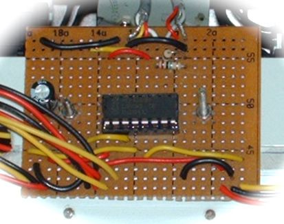
The board below multiplexes the analog signal from each accelerometer channel, in order to use a single analog input on the CM-510 Board.
For time reasons I've implemented both boards quickly by manually building the circuit tracks.
In more relaxed circumstances I would have made the same boards by PCB photo-etching.
Infrared Rangefinders
Terrain need to be analyzed in order to know if it's possible walking over it.
If the terrain roughness is high, it is avoided: the robot turns left or right searching for a better path.
The key concept adopted to detect if a terrain is too rough is this: robot needs a planar surface in order to climb over it without possibility of falling.
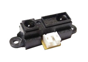
In order to understand if terrain is planar, some IR rangefinders have been used. This sensors are produced by SHARP, and the model is GP2D120X.
Main specifications GP2D120X Measuring distance range 3 - 40 cm Output terminal voltage 0.25 – 0.55 Average supply current 33 - 50 mA Operating supply voltage 4.5 – 5.5 V
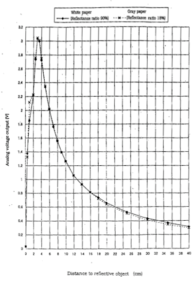
The output distance characteristics of sensor is shown in the picture below.
As we can see , the characteristic is not linear.
In order to take correct distances (in cm ) from the sampled values, I wrote a lookup table with 17 values and the corresponding tension value (represented as number )
unsigned short sharp_calib[17][2] =
{
{63,40},
{71,35},
{85,30},
{106,25},
{132,20},
{153,18},
{165,16},
{192,14},
{214,12},
{257,10},
{286,9},
{319,8},
{360,7},
{415,6},
{480,5},
{562,4},
{613,3}
}
The C function (used in the firmware code):
float readSharp_cm(unsigned char addr) interpolates the values in the lookup table, converting the tension value to distance in centimeters.
Four rangefinders are disposed onto a SensorBar horizontally fixed on the head of the robot, as we can see in the picture below.
Three of these sensors point straight towards the terrain in front of robot, analyzing terrain’s surface by sensing the distance from bar in three different points.
One sensor points in the march direction and is used to detect obstacles.
The sensors are disposed in this way:
- two in the center of the bar (one pointing down, one pointing forward)
- on in the left limit of the bar (pointing down)
- one in the right limit of the bar (pointing down)
Robot takes samples from all three sensors, and then compares them: If the distances are all the same (with a little tolerance), terrain is walkable. If the difference between right and center distances is high, robot turns slightly right If the difference between left and center distances is high, robot turns slightly left.
Before using this approach, I tried to take distances with a single sensor turret, actuated by another Dynamixel servo, but this solution has revealed to be too slow and power consuming, and was abandoned.
As said before in the Introduction of this thesis, this sensor-bar has been conceived thinking at the embodiment concept: it moves with the robot body, giving automatically the sensors the best point of view (in order to have a good perception of terrain and obstacles) automatically. Sensor-bar position and orientation change according to the body configuration, which in turn changes according to the interaction with the environment.
3-axis Accelerometer
In order to know the robot inclination with respect to gravity force vector, a 3-axis accelerometer has been used.
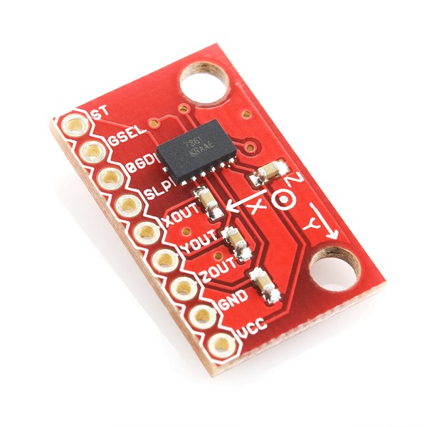
This sensor is produced by Freescale Semiconductor and the model is MMA7361 .
MMA7361
Low Voltage Operation 2.2 V – 3.6 V
High Sensitivity 800 mV/g @ 1.5g
Selectable Sensitivity (±1.5g, ±6g)
Low Current Comsumption 400 µA
Table 4: Accelerometer - MMA7361
I bought a ready to use “breakout-board” with sensor yet mounted on: you can see it in the photo above.
In this application the selected sensitivity is ±1.5g
The sensor has been mounted on the chassis, the most possible near to the center of mass of robot.
The robot center changes as the body joint moves, so a perfect positioning of the accelerometer has not been possible, but this was not a problem.
The accelerometer orientation is:
- x axis points towards robot forward sense of march, horizontally with respect to floor
- y axis is disposed horizontally with respect to floor, pointing to the left of robot
- z axis exactly in vertical position, pointing against gravity force vector.
The convention I used is to consider each axis in standard orientation when it is parallel to the plane normal to gravity vector.
For each axis, the implemented controller computes the displacement_angle from standard orientation.
The method used to determine this displacement_angle is very simple: Each of three channels values are normalized with respect to the gravity force When robot is in standard position, values are 0 for y,x channels, 1 (100% gravity force) for the z channel.
The orientation of each axis is computed as:
displacement_angle = arcsin(channel_value_N)
where channel_value_N is channel value normalized to gravity module.
Each channel value is equal to cosin(gamma), where gamma is the angle between the axis and the gravity vector
Computation of displacement_angle:


channel_value = g * cosin(gamma)

but we want to know the normalized value , so channel_value_N = channel_value /

g = cosin(gamma)

The standard position is 90° wrt gravity vector, so the displacement_angle, we call it delta, is:

delta = 90° - gamma

so

gamma = 90° - delta

so

channel_value_N = cosin(90° - delta)

Knowing that

sin(delta) = cosin(90° - delta)

we can  say

channel_value_N = sin(delta)

and finally

displacement_angle = delta = arcsin(channel_value_N)
Power
Transformer
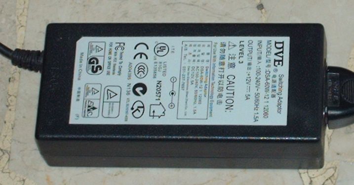
Robot has been powered by AC-DC transformer during the development phase. The transformer I used has this specifications: Output Voltage 12V
- Max current 5A max
Batteries
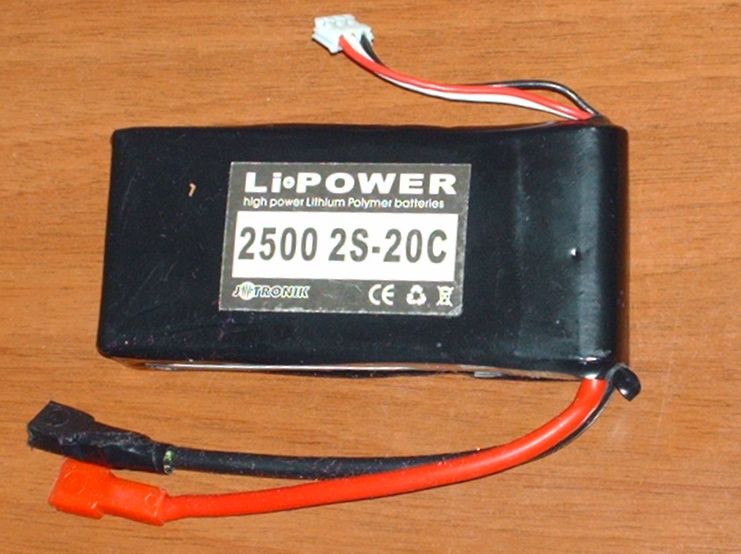
When the robot development has been completed, robot has been equipped with a couple of 2-cells lithium polymer batteries.
Batteries specifications:
- Output Voltage 7.5V
- Battery capacity 2500 mAh
Due to the lower tension of battery with respect to transformer, servo’s speed has been slightly increased in order to ensure a sufficient torque
Firmware
The implemented firmware was initially conceived to be the only program to control the robot.
After some testing, the used microcontroller has revealed to be too less powerful in order to obtain an acceptable loop speed and a sufficiently complex computational capability. A complex control like motion planning needs a more performant computational system.
I decided to mantain a fast reactive behavior based control in the main loop, adding a serial communication phase in order to allow data exchange with external control hardware, like a PC. A deep analysis of the behavior based control in mobile robotics can be found in a recent work from L. De Silva and H. Ekanayake [18]: they discuss several behavior control paradigms, including the subsumption.
In remote control applications, a simple control like this will act as a cerebellum, assisting the remote user in the motion control. A recent work on this topic has been made by Shigang cui, Zhengguang lian, Li zhao, Zhigang bing, Hongda chen [19].
They discuss several behavior control paradigms, including the subsumption.
The implemented loop resulted to be very fast, and sufficient to manage the most critical behaviors, like falling prevention and obstacle climbing.
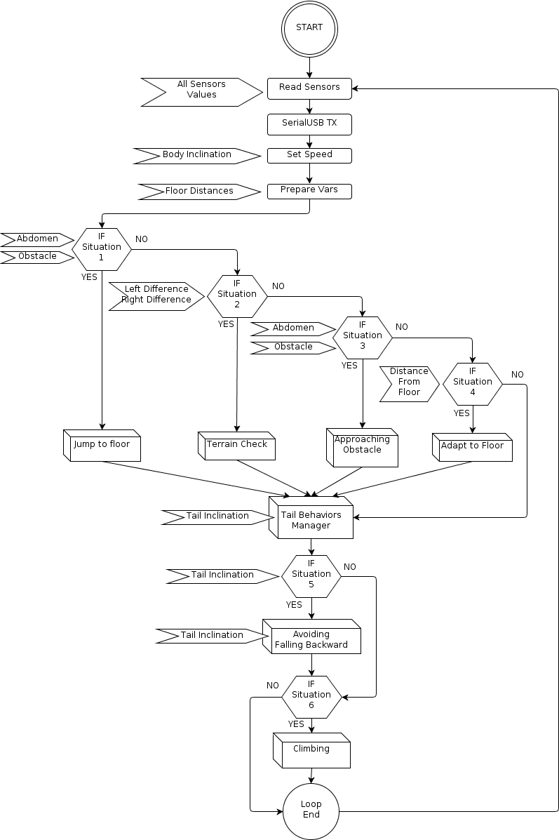
The main control loop consists of this macro blocks:
- Read and Communicate Sensors Data
- Set Speed According to Body Inclination
- Main Behaviors
- Jump Down Behavior
- Terrain Check Behavior
- Approaching Obstacle Behavior
- Adapt to Floor Behavior
- Walking Actions
- Go Backward
- Turn Left
- Turn Right
- Restart Walking
- Stop Walking
- Tail Control Section
- Tail Behaviors Manager
- Tail Behavior 1: Avoiding Falling Backward
- Tail Behavior 2: Climbing
Read and Communicate Sensors Data
The first thing to do in the main loop is reading sensors, and communicating them to the eventual external hardware through the serial-usb link.
Reading Sensors
This is done using this funcion:
- void readAllSensors(Sensors *s);
It reads all sensors data saving them into a Sensors structure.
The above function calls a specific read function for each sensor:
- float readSharp_cm(unsigned char addr);
It reads the value of Sharp sensor mapped at address addr and convert it to distance in centimeters.
Each address indicates a channel on the distance sensors multiplexer.
- float readAccDeg(unsigned char addr);
It reads the angle value from the Accelerometer Channel at address addr, and converts it to degrees.
Each address indicates a channel on the accelerometer multiplexer, and each multiplexer channel correspond to a single channel on the accelerometer.
Accelerometer, as seen before, has 3 channels, one for each axis.
Communicating sensor data
The communication is performed through a serial link in asynchronous mode, at a baudarate of 57600 bps.
The serial format is 8bit, no parity, 1 stop bit.
The data format is the following:

FC <FC>\tGC <GC>\tGL <GL>\tGR <GR>\tZ <Z>\tX <X>\tY <Y>\tAD <AD>\tTD <TD>\n

and this is the meaning of the tags:

<FC> : Distance in cm from Central Front Sensor
<GC> : Distance [cm] from Central Ground Sensor
<GL> : Distance [cm] from Left Ground Sensor
<GR> : Distance [cm] from Rigth Ground Sensor
 <Z> : Normalized [adim] value from Z axis Channel on Accelerometer
 <X> : Normalized [adim] value from X axis Channel on Accelerometer
 <Y> : Normalized [adim] value from Y axis Channel on Accelerometer
<AD> : Abdomen Inclination angle [deg] with respect to the robot body
<TD> : Tail Inclination angle [deg] with respect to the robot body
This data is intended to be read from the serial-usb interface using a sscanf function
implemented in any programming language.
All transmitted values are integers ( %d in C, C++ format ).
This is the output we get connecting to it :
...
FC 39 GC 17 GL 19 GR 19 Z 932 X -24 Y 43 AD -34 TD -37
FC 39 GC 16 GL 18 GR 18 Z 1000 X 48 Y 92 AD -34 TD -37
FC 39 GC 15 GL 18 GR 19 Z 1000 X 54 Y 37 AD -34 TD -37
...
Set Speed According to Body Inclination
In order to adapt the servomotors torque to the current ground surface, the robot must increase their speed according to the vertical inclination of the robot body.
If the inclination value is high and positive, the robot is walking uphill, so the torque must be increased.
The following instruction sets the nominal speed for all whegs servos: dnspeed
(Desidered Nominal Speed) : dnspeed = (600 + 4 *sensors.body_inclination_xg);
Dynamixel servos accept a speed value from 0 to 1023.
Here we set 600 as base-speed, then adding a variation proportional to inclination.
If the inclination is negative (robot walking downhill) the added variation will be negative, ending up with a speed value smaller than base-speed.
Main Behaviors
This behaviors determine the commands that will be sent to the whegs in the following Walking Actions section.
All this behaviors are exclusive, and they have descending priority, so that the first has the high one and the last has the lower one.
Each behavior has a trigger event that I call “situation”.
Before going to process the behaviors, some data must be prepared.
float ld = abs((int)(sensors.distance_floor_left – sensors.distance_floor_center));

float rd = abs((int)(sensors.distance_floor_right – sensors.distance_floor_center));
The above two instructions compute two difference values:
- ld : Left Difference This is the difference value between the left terrain distance sensor and the center terrain distance sensor
- rd : Right Difference This is the difference value between the right terrain distance sensor and the center terrain distance sensor.
This difference values will be used within the following behaviors in order to detect the current situation.
Jump Down Behavior
Situation 1:
Robot’s head is facing floor with an abdomen inclination inferior to -45 ° with respect to gravity force vector
AND distance from floor along the view axis is less than 30 cm.
In this situation the robot will probably crash his head to the floor if it doesn’t lift it Instantly, so the first command is to stop walking.
This situation requires that the distance from floor is less than 30 cm, so that the robot could “jump” toward floor without destroying itself.
Behavior 1:
Then the robot lift up the abdomen until it exits from this situation.
Code
if (sensors.abdomen_inclination_g < -45 && sensors.distance_front_center < 30){
stop();//STOP ROBOT
while(sensors.abdomen_inclination_g < -45 && sensors.distance_front_center < 30)
  {
  //LIFT ABDOMEN
  dpAbd = dpAbd + 1;
  setAbdomenDeg(dpAbd, 1000);//Lift
  sensors.abdomen_inclination_g = getAbdomenDegG();
  sensors.distance_front_center = readSharp_cm(4);
  }
}
Terrain Check Behavior
This behaviors uses the Left Difference (ld) and Right Difference (rd) described before in chapter 5.3.
Situation 2:
Left Difference or Right Difference is greater than 8 cm.
This means that terrain is not uniform.
Behavior 2:
turn where the difference is smaller.
Code:
if(ld > 8 || rd > 8)
{
 if (ld >= rd) {turnR = 1; turnL=0;}
 if (ld < rd) {turnL = 1; turnR=0;}
}
Approaching Obstacle Behavior
Situation 3 :
There is an obstacle near in front of the robot in central position.
Obstacle is considered near if distance is less than 15 cm.
Behavior 3 :
climb over the osbtacle.
The sequence of actions to perform is :
1. stop walking
2. lift head (abdomen) until obstacle diappears and abdomen inclination doesn't
    exceed 80°. This limit has been imposed in order to avoid vain climbing efforts
    on almost perpendicular walls.
Code:
if (sensors.distance_front_center <  15)
{
  stop();
  while(sensors.distance_front_center < 15 && sensors.abdomen_inclination < 80)
  {
   if (dpAbd > 80)dpAbd = 80; //Upper Bound setAbdomenDeg(dpAbd, 200);//Lift up
   abdomen sensors.distance_front_center = readSharp_cm(4); //read distance
  }
}
Adapt to Floor Behavior
Situation 4 :
Distance from floor is greater than 23 cm
This happens when the abdomen is too high, or when robot approaches a descent .
In order to have a good sensing of the terrain the sensors array should point the floor perpendiculary (and so abdomen should be parallel to terrain).
Due to the geometry of robot (his height is about 23 cm), lowering abdomen until it's 23 cm distant from floor will put it parallel to floor surface.
Behavior 4 :
Lower the abdomen until distance of  head  from floor is less than 23 cm
or it's tilted down more than 75°
Code:
if(sensors.distance_floor_center > 23 )
{ // Floor too distant ..
  stop(); //stop walking
  while(sensors.distance_floor_center > 23 && sensors.abdomen_inclination > -75)
  {
    dpAbd = dpAbd – 1; // Lower down Abdomen
    if (dpAbd < -75)dpAbd = -75; // Limit value
    setAbdomenDeg(dpAbd, 200);//send command to servomotor
    sensors.distance_floor_center = readSharp_cm(6);
  }
}
Walking Actions
The purpose of this section is to send commands to servomotors, in order to perform the movements requested by the previous behaviors section.
The first instruction of this section is a control statement that checks if the robot should be walking or not.
This is accomplished by reading the value of a condition variable called walking.
This condition variable is set within the previous behaviors section.
Code:
if (walking==1)
{
  …
}
The other condition variables used to control this section are:
turnL//Turn Left
turnR//Turn Right
Go Backward
The way behaviors inform this section that the robot must bo backward is just enabling both turn condition variables : turnL and turnR.
Code:
If(turnL && turnR)
{
  int i ;
  for (i=0;i<3;i++){//Go Back
     dxl_write_word( whegs_sx[i], P_MOVING_SPEED_L, 1424 );
     dxl_write_word( whegs_dx[i], P_MOVING_SPEED_L, 400 );
     _delay_ms(20000);//Mantain behavior
     //Disable behavior..
     turnL = 0;
     turnR = 0;
  }
}
Turn Left
Turning Left is accomplished by going backward with the left train of whegs, keeping still the right one.
Behavior is mantained for a while, and then condition variable are cleared.
if(turnL)
{
  int i ;
  for (i=0;i<3;i++) //iterate on all servos {
     dxl_write_word( whegs_sx[i], P_MOVING_SPEED_L, 1424 );
     dxl_write_word( whegs_dx[i], P_MOVING_SPEED_L, 0 );
     _delay_ms(20000);//Mantain behavior
     //Disable behavior..
     turnL = 0;
     turnR = 0;
  }
}
Turn Right
Same as Turn Left.
if(turnR){
  int i ;
  for (i=0;i<3;i++){
     dxl_write_word( whegs_sx[i], P_MOVING_SPEED_L, 0 );
     dxl_write_word( whegs_dx[i], P_MOVING_SPEED_L, 400 );
     _delay_ms(20000);//Mantain behavior
     //Disable behavior..
     turnL = 0;
     turnR = 0;
  }
}
Restart Walking
This section is needed to make the robot restart walking in two cases:
- it was stopped before
- it was turning
if (!(turnL + turnR)){//If not turning
  go_fwd();//Go forward
}
Stop Walking
If the walking condition variable is not set, the robot just stops walking.
If (walking==1)
{
  …
}
else
{
  stop(); //Stop Walking
}
Tail Control Section
In this section we control the tail, in order to help robot to accomplish some tasks.
This part is located after the Walking Actions section, because it do not modifies any walking control variable.
Tail Behaviors Manager
This section acts like a behavior manager, it mantains a behavior until it accomplishes its task.
It checks if tails has reached (with little toelrance) the desidered position and, in positive case, it disables the torque on tail servomotor.
Then it disables all tail behaviors by clearing dpTail control variable.
// Check if desidered Tail position (if it was set) has been reached
if(dpTail != -1 && abs((int)dpTail - (int)pTail) < 50)
{
  dxl_write_word( 1, P_TORQUE_ENABLE, 0 );
  // Disable Torsion Servo
  // Needed to shut off tail behaviors
  // activated in previous loop cycle
  dpTail = -1; //disable desidered Tail position
}
Tail Behavior 1: Avoiding Falling Backward
Situation 5 :
• Tail is high (wrt body)
• Abdomen isn't low (wrt body)
• Body is tilted up more than 45° with respect to gravity vector
In this situation the robot is likely to fall backward, so robot body must be put in a less dangerous configuration.
Behavior 5 :
Lower the tail until it’s almost in line with body (horizontal position)
Putting tail in line with body makes the back of the robot to lift up.
In this way robot’s center of mass is moved forward, towards the central position, putting the whole body in a safer position.
Code:
if ( parallel && pTail < 300 &&  // Tail is high
     getAbdomenDeg() >-10 && // Abdomen isn’t low (wrt body)
     readAccDeg(1) > 45) // Body is tilted up more than 45 deg wrt g
{
   //avoid falling backwards
   dpTail = 500;
   dxl_write_word( 1, P_GOAL_POSITION_L, dpTail );
   dxl_write_word( 1, P_MOVING_SPEED_L, 210 );
}
Tail Behavior 2: Climbing
Situation 6 :
• Tail is slightly up (wrt body)
• Abdomen is slightly low (wrt body)
• Body is tilted up more than 60° with respect to gravity vector
In this situation, robot's body is very tilted up, and abdomen is slightly tilted down.
This means that robot is climbing over an obstacle.
Behavior 6 :
Lower the Tail until it’s quite lower than the horizontal position.
If the tail is slightly upper than the horizontal position, it should be lowered down, in order to help robot in the climbing task.
Lowering tail helps because in this way the robot’s back is lifted up, and this moves the center of mass forward, causing the frontal whegs to exert a greater pressure on terrain.
Great pressure on terrain ensures more grip, and so robot can easily bring its body forward, accomplishing the climbing task.
if ( parallel && pTail < 450 && // Tail is slightly up
     getAbdomenDeg() < -20 && // Abdomen is slightly low
     readAccDeg(1) > 60 ) // Body is tilted up more than 60 deg wrt g
{ //climb
   dpTail = 712;
   dxl_write_word( 1, P_GOAL_POSITION_L, dpTail );
   dxl_write_word( 1, P_MOVING_SPEED_L, 210 );
}
